I. Preparation Before Installation
Drawing Preparation
Prior to installation, ensure that the spindle assembly drawings are prepared or that the spindle shaft system structure is clearly understood. Confirm all necessary components and the specific bearing installation method applicable to the spindle.
Spindle Components Preparation
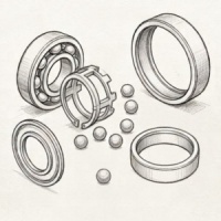
Before mounting the bearings, thoroughly clean the shaft, housing, and all associated components. Surfaces must be free from burrs, protrusions, or any contaminants. Verify the dimensions of the shaft and housing bore to confirm they meet the assembly specifications.
For spindle assemblies that incorporate spacers between bearings, check both the parallelism and height variation of the inner and outer spacers. The parallelism should not exceed 0.003 mm, and height difference must be within 0.002 mm.
Bearing Preparation
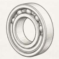
Open Bearings: These bearings must be cleaned before installation. Hold the inner ring while keeping the outer ring surface facing upward, and rotate the outer ring during cleaning. Alternatively, place the bearing at an angle in a container with the outer ring facing downward and rotate the inner ring. Suitable cleaning solvents include clean No. 120 aviation gasoline, kerosene, or anhydrous alcohol. Once dried, apply the appropriate type and quantity of grease as specified in the bearing product catalog.
Sealed Bearings: Do not clean sealed bearings. Simply wipe the outer surface clean before use.
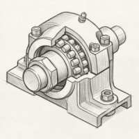
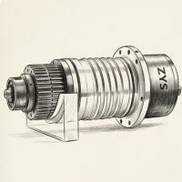
II. Bearing Installation
Installation of Bearings
After confirming the correct orientation of the bearings, use an induction heater to warm the bearings before installation. The recommended heating temperature is between 70°C and 80°C. Install the bearings in accordance with the spindle shaft structure and in the correct sequence.
Locknut Tightening
Only tighten the locknut after the shaft has completely cooled down. Use a torque wrench to apply the manufacturer-recommended tightening torque.
Cover Installation
When installing the bearing outer ring cover, tighten the bolts in a crisscross pattern over 2–3 stages. Prior to installation, ensure the gap between the end face of the cover and the bearing housing surface is maintained within a range of 0.02–0.04 mm.
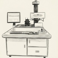
III. Inspection and Run-In
Precision Inspection
Before proceeding to full operation, manually rotate the spindle to check for smooth motion. Use a dial indicator to measure the shaft end accuracy, ensuring it aligns with the required installation precision standards.
Spindle Run-In Procedure
Prior to mounting the spindle on the machine, conduct a controlled run-in. Start by operating the spindle at 10%–15% of its maximum speed, then gradually increase the speed in 10%–15% increments. At each stage, maintain operation for approximately 30 minutes to ensure proper bedding of components.
Following these spindle installation guidelines ensures the optimal performance and longevity of your spindle system, especially in high-speed or precision machining applications.